Defender 90


Assembly
This remote control vehicle started off as an unassembled base kit with ABS plastic parts for nearly all components of the underbody chassis along with a generic brushed motor, electronic speed controller, etc.
To stimulate my critical thinking, I assembled the kit without viewing the instructions to withhold a heightened interpretation of the mechanical assembly. This allowed for me to have a better understanding of what needs to be modified and improved as I prepare it for off-road purposes that requires reinforced components for greater performance, functionality, and reliability in the long run as its durability is challenged.
Modifications and Refinement
Suspension Components
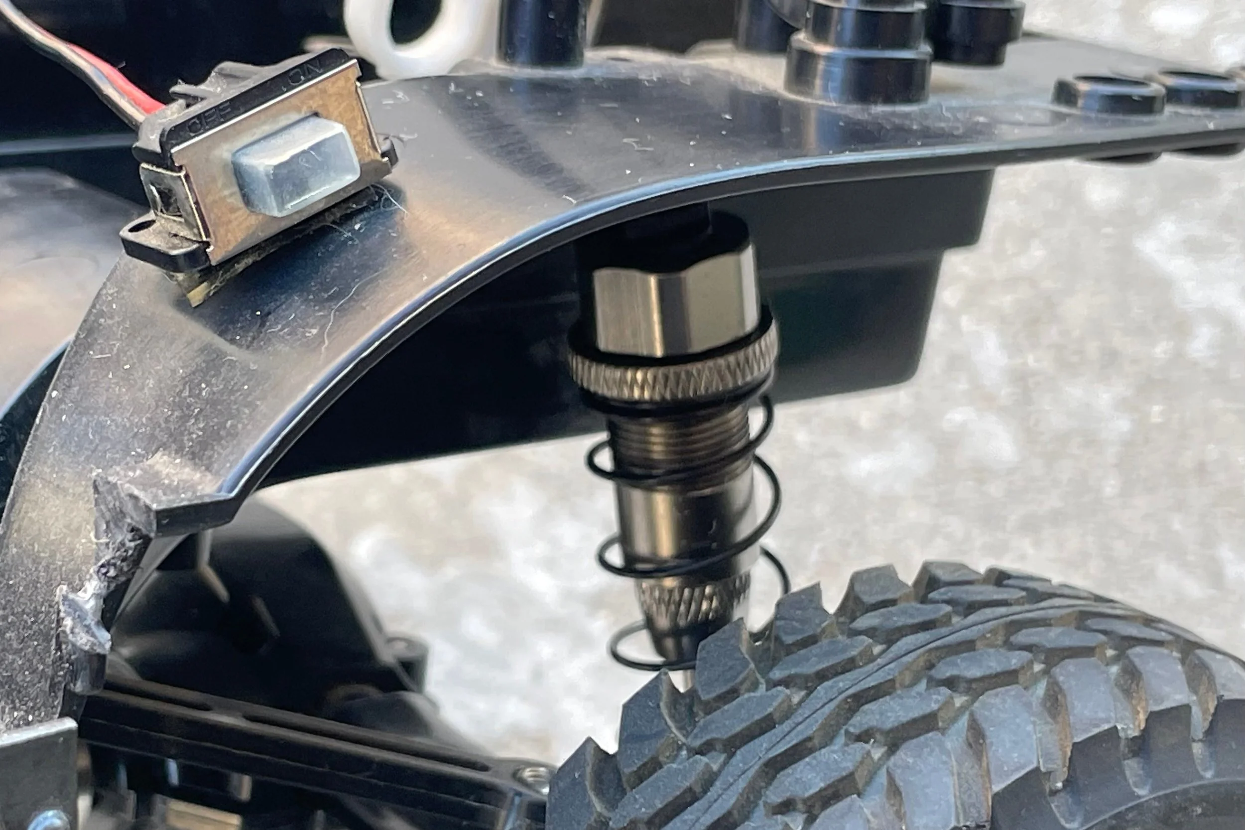
As shown, I upgraded the stock plastic suspension to milled aluminum with a proper damping system. After road analysis, I noticed the original shocks were too stiff so I lowered the spring rate and softened the damping. The silicone damping fluid in the original shocks were at a value of 600 centipoise (cP) so I bled it out and replaced it with silicone oil of 300 cP. For the springs, I went to my local hardware store and used my intuition to pick out a set of springs that felt significantly less resistive compared to the original springs.
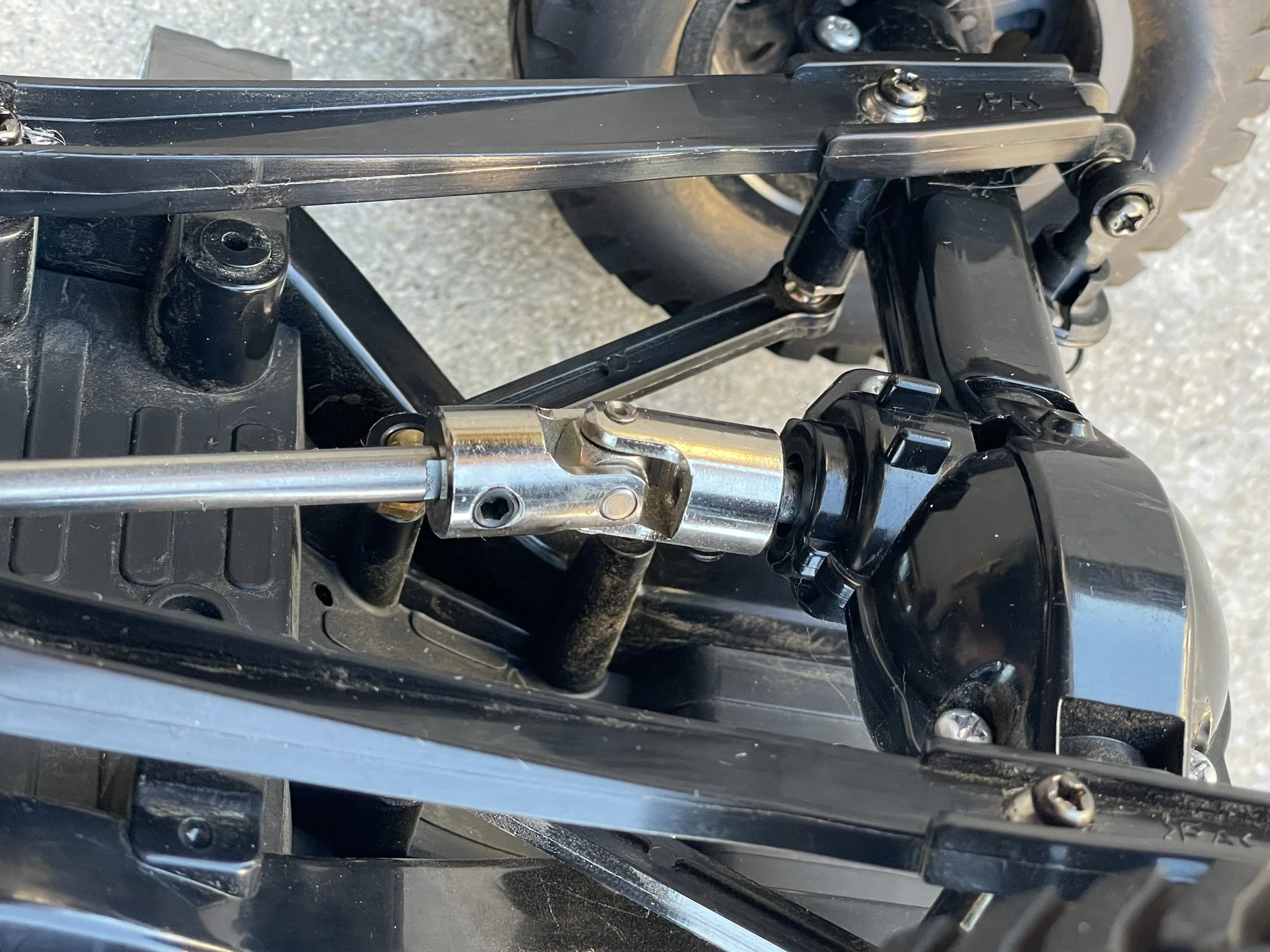
As of now, I have no intent of replacing the plastic trailing arms and control arms since they have been very durable and allows for the car to flex without compromising rigidity. None of the steel bushes have rusted yet so they will be in use until further notice.
Powertrain Components
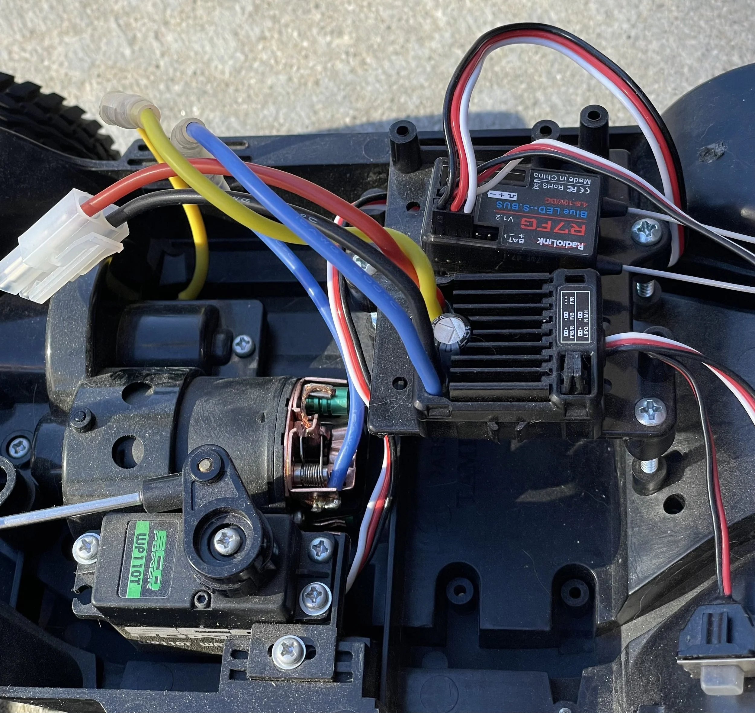
During testing, I noticed that the original servo had a high turning speed which was an issue for the maneuverability and control, especially during rock climbing. For better precision under load, I upgraded it to one with an operating speed of 0.16/60° sec and a dynamic torque value of 280 oz-in.
I upgraded the motor to a brushless one with a much lower top out speed and comparably higher torque. Without proper specifications from the manufacturer, I tested both motors on a homemade 35° incline to see which motor had a higher torque output.
Wiring, Lighting, and Paint
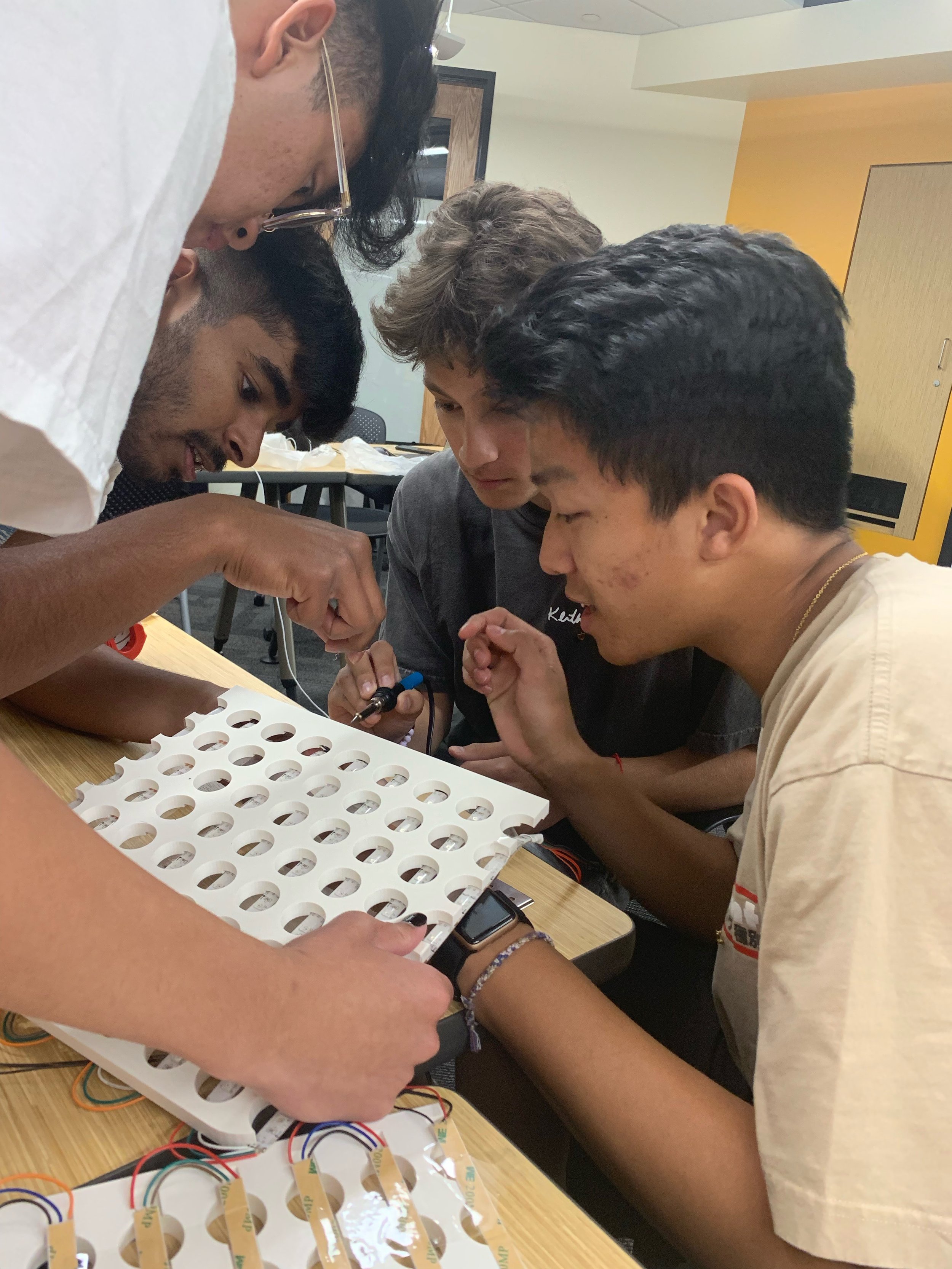
For the exterior lighting of the front headlights, rear taillights, and roof fog-lights, I soldered LEDs to a wiring system that ran underneath the body of the vehicle. All of the individual lights met at a singular module that connected directly to the battery pack.
The ABS plastic clear shell of the Defender’s silhouette was spray painted in two-tone British Green and Titanium White. The windows are smoked with mesh decorations for a realistic effect.


LED Gameboard
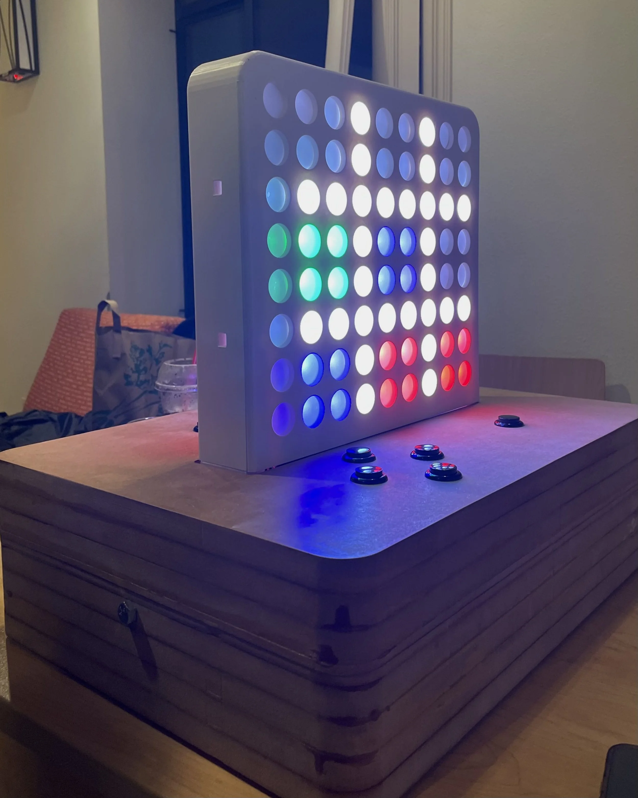
My team of a few curious engineers envisioned a modern take on a retro gaming system that simulates the touch and feel of classic arcade machines. With tactical buttons and a solid wooden build, the player can experience the nostalgic sensation of retro gaming.


Concept Development
Problem Definition
At engineering social events, people often find themselves bored, standing around in a crowded room. My team and I envisioned a simple yet effective way to keep fidgety engineers stimulated, involved, and entertained. We decided to design and build an arcade system that is minimal, streamlined, and functional.
User Needs Analysis
We interviewed all members (ages 18 to 22) within our professional engineering organization to better understand collective user needs and to identify preferences and challenges. By engaging directly with potential users, our hardware design team division was able to map a diagram that assesses the feasibility of meeting core expectations based on given constraints (time and budget). A summarized user need analysis based on internal surveys and group-based interviews are as followed:
→ Requires no instructions or prior knowledge of the system’s interface, must be straight-forward and user friendly.
→ Majority of our user base (~70%) enjoy tactical buttons, especially in dimmer settings where touch is the dominant sensation.
→ Around 55% of users prefer to play standing up both in/outdoors.
→ The hand sizes/positions of both male and female users were selected from an anonymous pool of ~25 people to gauge button placement.
→ Design for serviceability must be considered, as determined by the electrical engineering team for accessible maintenance.
“Cup pong gets repetitive sometimes... is there something else to do???”


Manufacturing Development
Based on our given constraints (access to equipment, budget, and time), our team considered the advantages and disadvantages of various additive manufacturing methods by assessing possible failure modes, material properties, and durability utilizing FEA.

Photo Gallery
Hardware Design
Concepts, Constraints, and Specifications
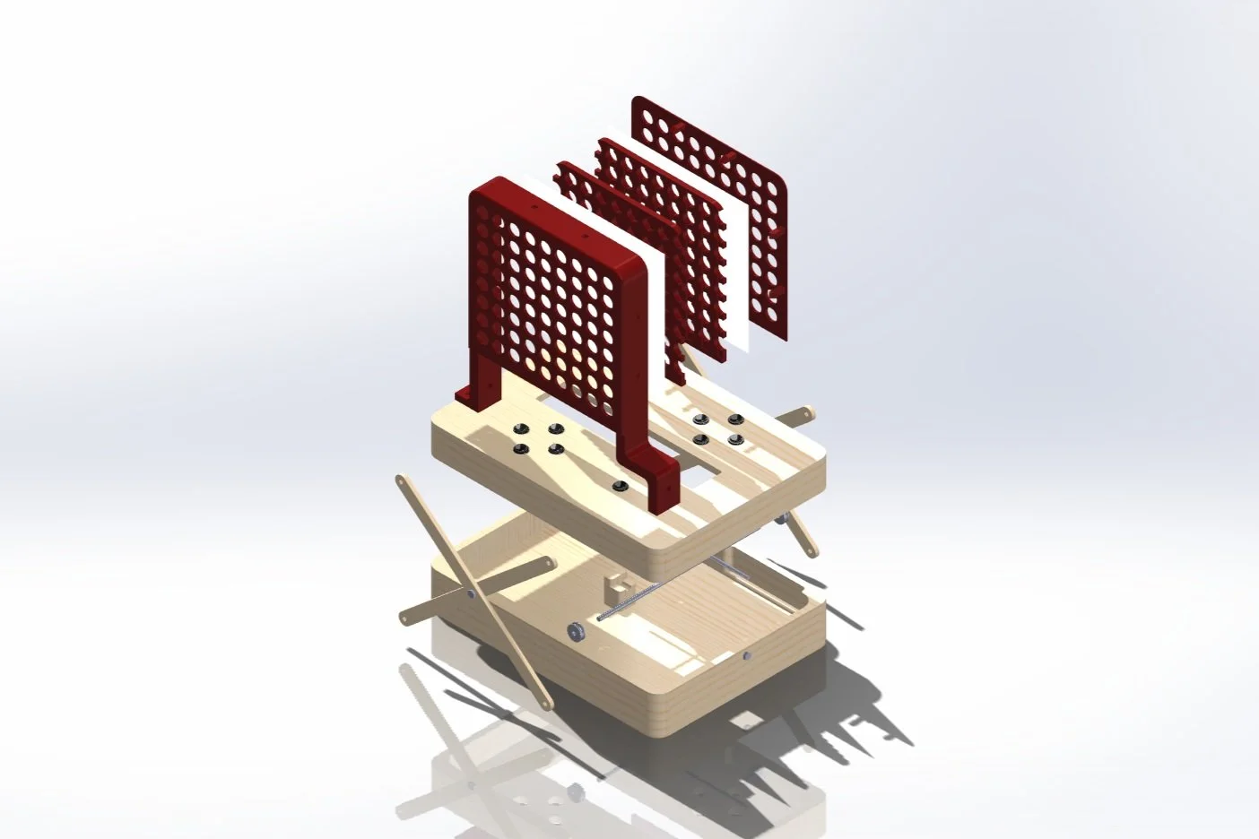
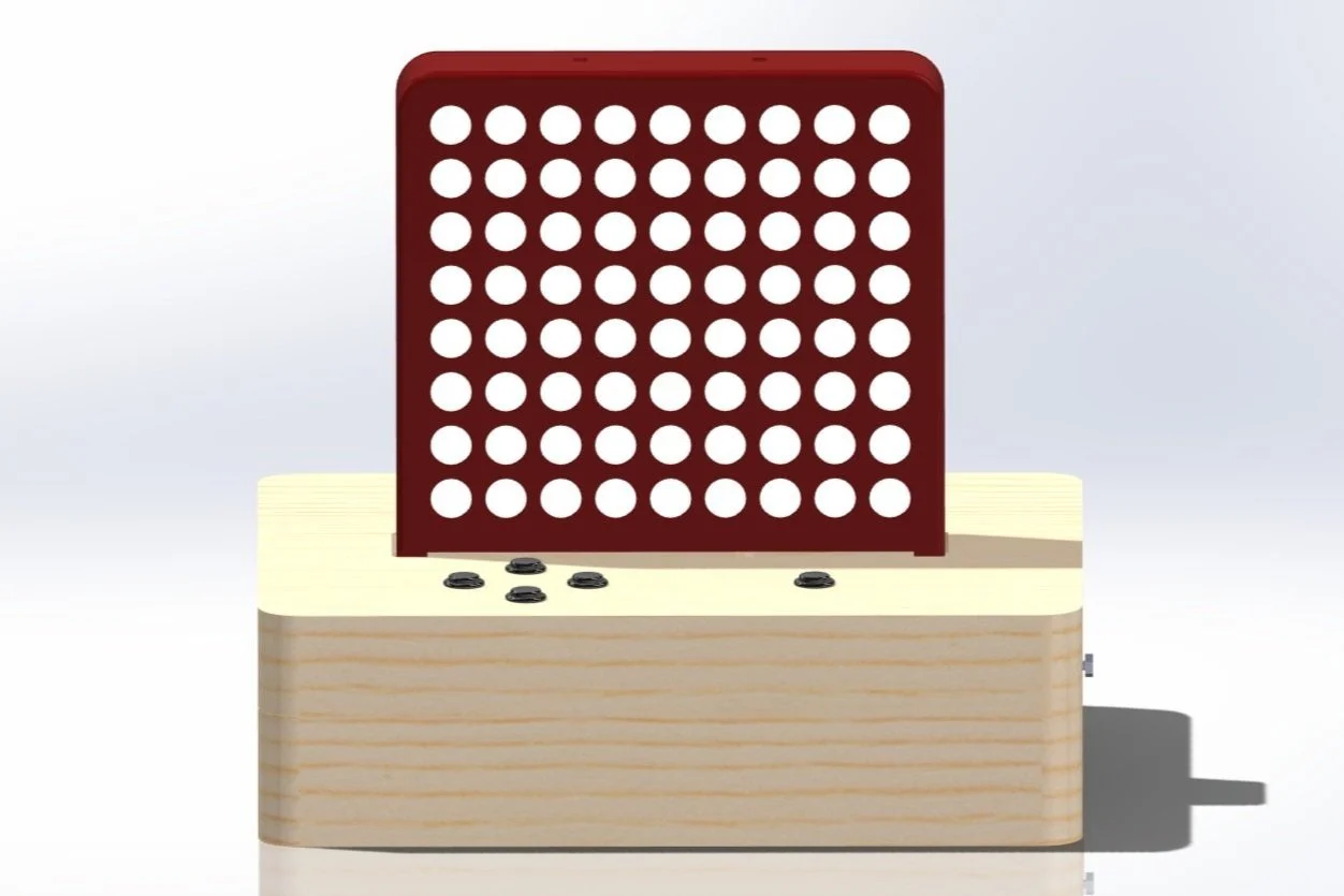
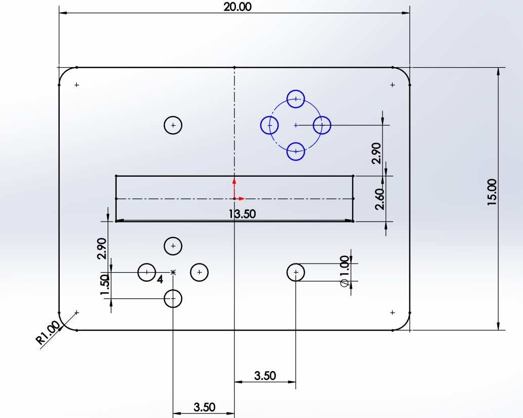
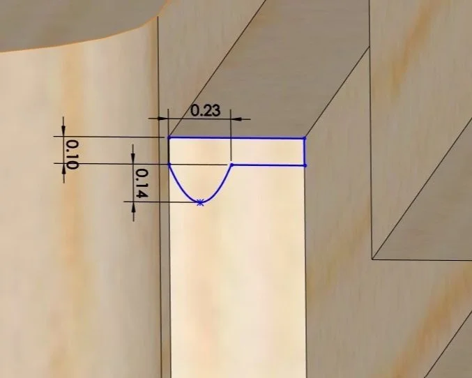
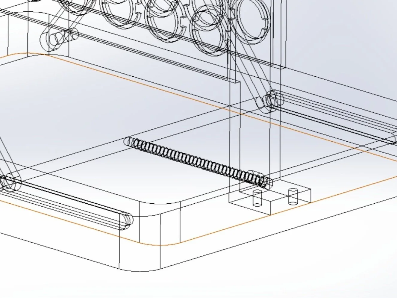
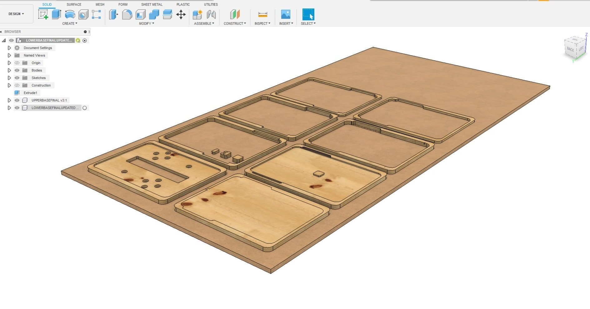
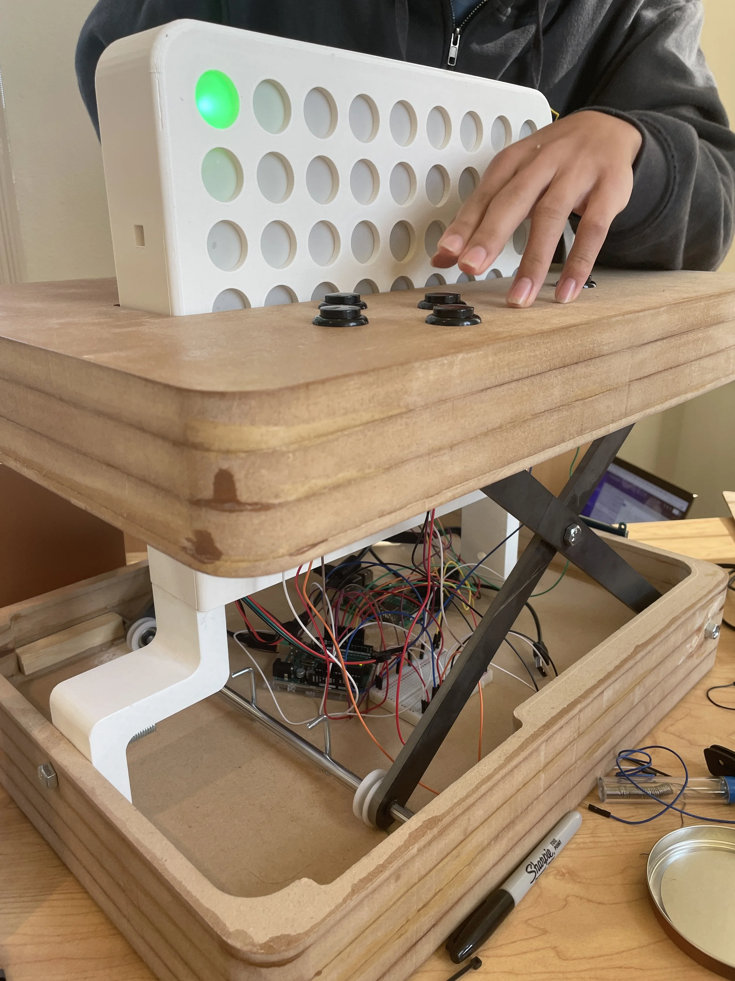
→ Design for Serviceability was incorporated into the design process to ensure convenient access to internal components for maintenance. The base of the game board is separated into two sections- the upper and lower base. The lower base houses all of the electronic components (wiring harness, arduino, battery pack, etc). The upper base has incisions for the buttons and the LED grid board. A wheel-bearing rail system allows for the scissor-lift mechanism to move in the z-axis.
→ Design for Assembly simplified the product structure. Snap-locks allowed for a reduction of the need for tools and hardware. Standardized materials were used for cost-reduction, expedited fabrication for a replacement part, and a more streamlined appearance.
→ Waterproof, to ensure all internal electronic components are not exposed to liquid spillages. Rubber seals and gaskets are placed where seepages can occur (buttons, gaps) along with a two-stage water-repellent coating on the exterior of the system.
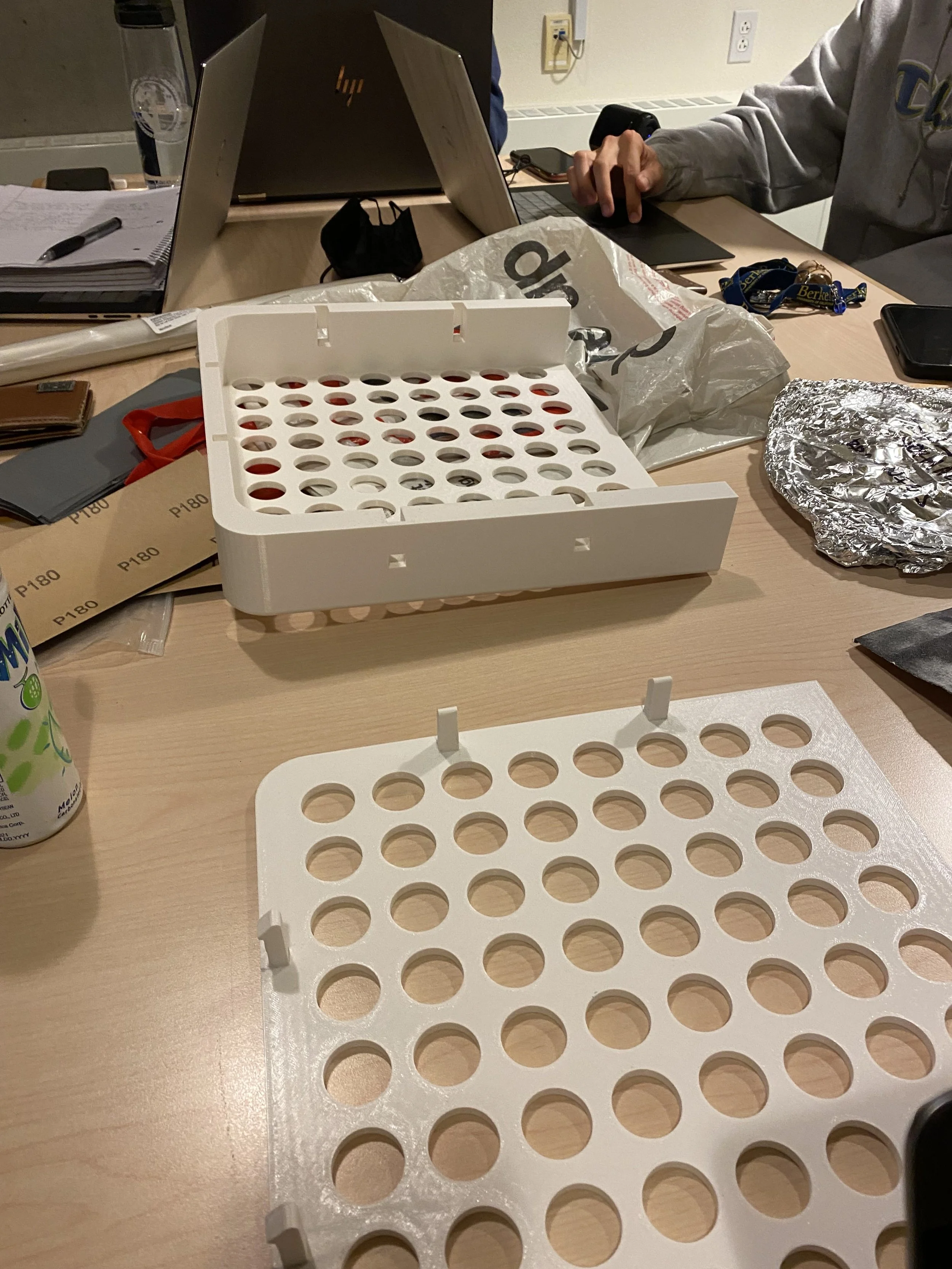
→ Light dispersion was critical since in the initial prototypes, light from neighbor cells would bleed into each other. To prevent light bleeding, we designed the main LED grid board to be comprised of four sub-sections. The LED strips are sandwiched in between the two innermost pieces of the assembly, isolating each individual light module to its respective grid with a frosted acrylic pane in between.


Demo Video


For more details, check out our project website!
Scrubtious Bottle Cleaner

Concept Development
Problem
Many reusable bottles have a tapered and narrow opening, making it very difficult for people to reach their hands or sponges in to properly clean the insides of the bottle. This leads to funky smelling bottles and underlying sanitary concerns. In a team of six engineers, we created a solution to the proposed problem by designing and developing a cleaner that reaches the bottle of the bottle while scrubbing the insides all at once.
The Product
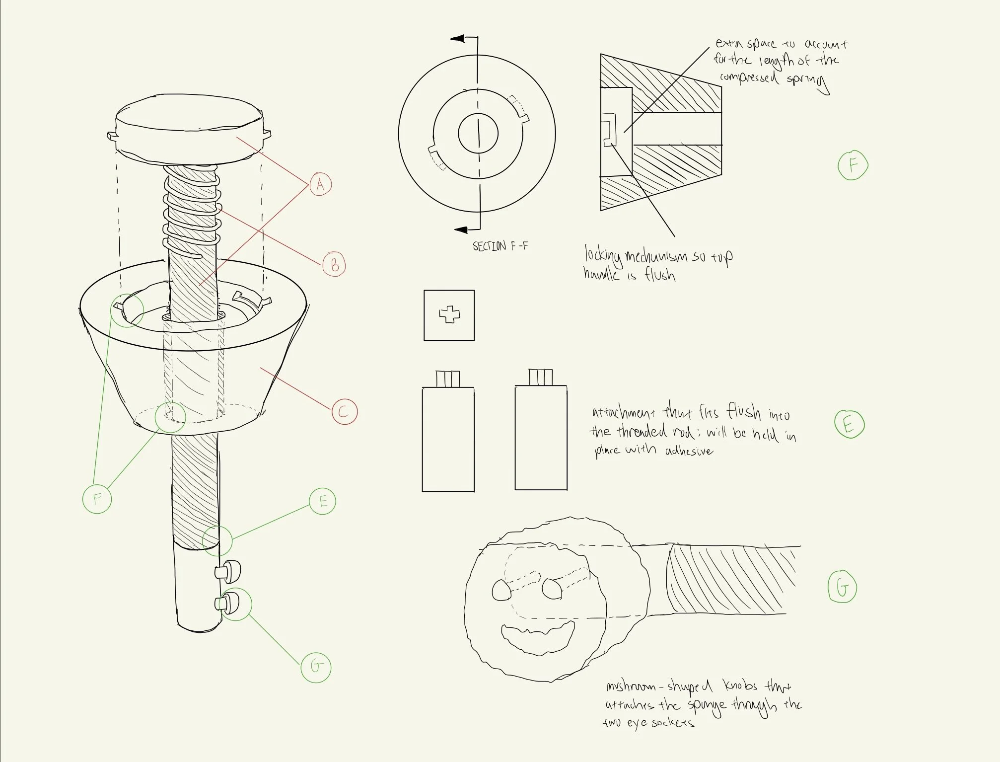
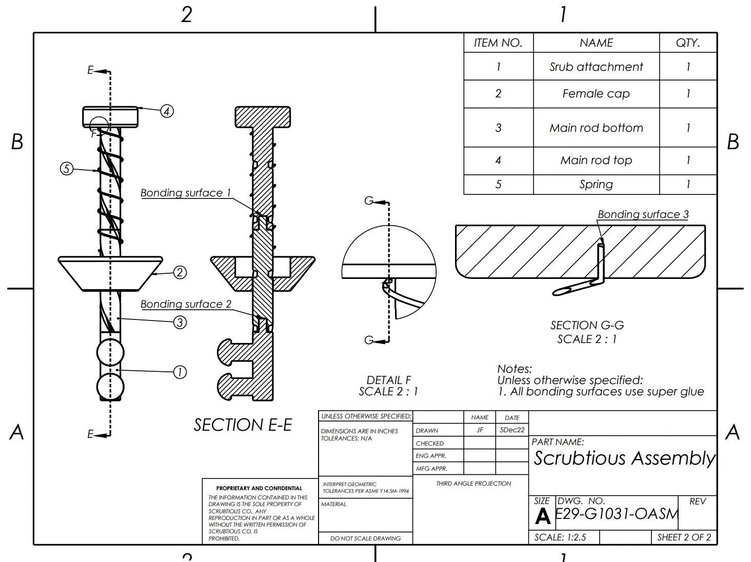
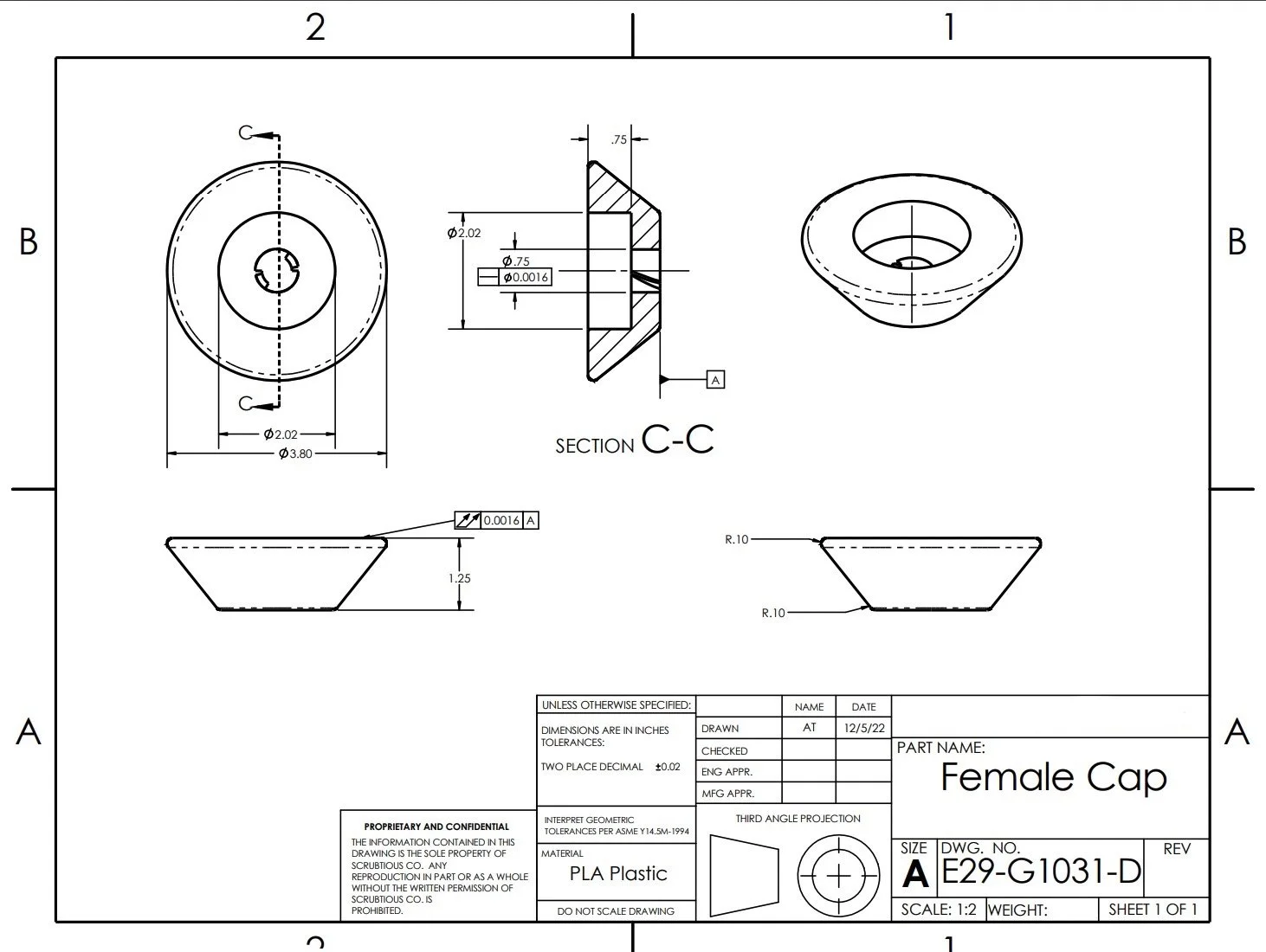
Scrubtious is a portable bottle cleaner that cleans the hard-to-reach areas inside of a bottle. It works by attaching a Scrub Daddy to the bottom attachment, which then spins as the cleaner is pushed down using a syringe-style mechanism with spiraling threads. The mechanism is spring loaded, ensuring that it will spin back to its initial state after reaching the bottom.
Design Constraints and Manufacturing
Before modeling the design on SolidWorks, we sketched a mockup of key design constraints and features that we wanted to implement into the assembly.
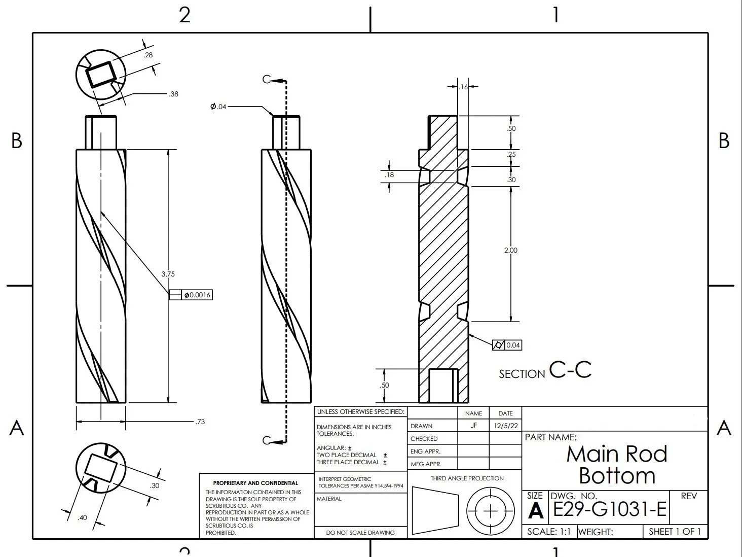
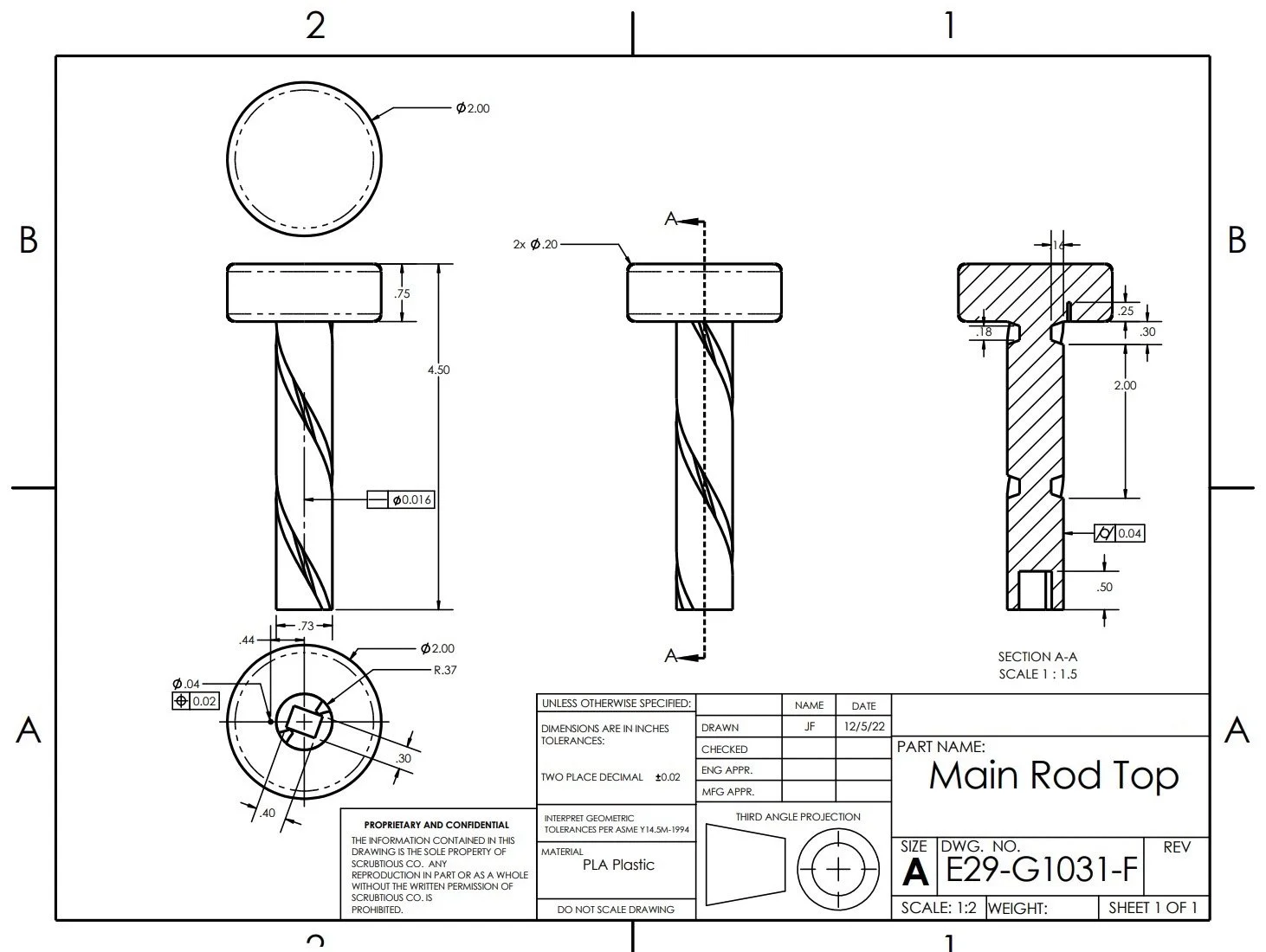
A constraint that we had to work around was the print dimensions of the 3D printers that were available on campus. Due to the length of the design exceeding the maximum print size of around 10 in, we sliced the main assembly into two separate pieces- the threaded shaft and the bottom attachment.
The piece that slides in between the threads had to be smaller than the width of the threads. Due to the inaccuracy of the 3D printers, we sanded down the piece to make sure that the mechanism could spiral down the threads smoothly
To connect the threaded shaft to the bottom attachment, we designed a plus-shaped insertion piece in order to maintain structural integrity as the assembly undergoes stress.
Engineering Drawings


Final Product

Additional Projects TBA
